In 2019, IEEE published 802.3cg, which added clauses 146 and 147 to its Ethernet 802.3 standard, which created 10BASE-T1S (short reach) and 10BASE-T1L (long reach). These two Ethernet flavors can serve vehicles and industry, respectively, where few wires take priority over high speed. Automotive Single-Pair Ethernet (SPE) 1000BASE-T still has a place in vehicles for infotainment and assisted driving. Many automotive and industrial sensors don’t need high-speed links but need data and power.
The automotive industry has shown interest in 10BASE-T1S because wires make up a significant percentage of a vehicle’s weight. Anything that reduces cabling helps with weight, cost, and energy efficiency. “Wiring is the third heaviest thing in the car,” said Craig Chabot, formerly of the University of New Hampshire Interoperability Lab (UNH-IOL) when EE World visited there in April 2024.
Vehicles currently use low-speed buses such as CAN, LIN, and FlexRay to carry data from sensors, while 1000BASE-T high-speed Ethernet handles infotainment systems and serves as an overall communications backbone (Figure 1).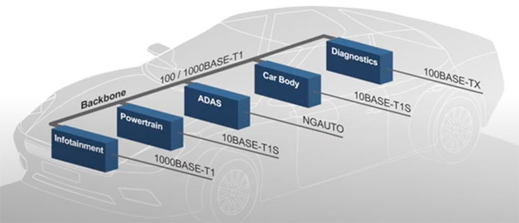
The low-speed buses work well, and development on them continues, but there’s a movement to replace them with 10Base-T1S, thereby bringing Ethernet throughout the vehicle. You can use the same protocol stack regardless of the physical (PHY) layer. Connecting low-speed devices such as powertrain sensors using Ethernet instead of traditional buses brings all communications under the high-speed Ethernet backbone.
10BASE-T1S buses can handle up to eight nodes per line, connected through shielded or unshielded twisted pairs. That makes it suitable for zonal architectures within a vehicle.
Without a switch to manage transmissions, how can multiple Ethernet nodes play together without interfering with each other? Nodes stay in a high-Z state when they’re not talking to Node 0, the coordinator. “PHY-layer collision avoidance (PLCA) is the biggest thing about 10Base-T1S,” said UNH-IOL’s Jason Sisk during EE World’s lab visit.
PLCA operates at the PHY layer and does not interface with the medium access control (MAC) layer or any other layers. PLCA initiates when Node 0 sends a 20-bit beacon to all other nodes. IEEE 802.3cg defines a transmit-opportunity timer on each node, which the node resets upon receiving the beacon. The beacon includes a node ID that’s independent of its Ethernet MAC address. This begins a transmit cycle, letting each node transmit only during its turn, or opportunity, whenever the beacon’s ID matches that of a given drop. If a drop doesn’t have data to send, it remains in a high-Z state and doesn’t place a load on the bus. If a drop has data, it sends a commit signal while others wait their turn. “If you want to transmit,” said Sisk, “you’re in a 50 Ω configuration. If you’re listening, you’re in a high-Z state.” Figure 3 shows how the beacon, commit, and data transmissions fit within an Ethernet frame.
“If you have a trunk and two end nodes,” added Chabot, “you’ve got 100 Ω matched over a 100 Ω trunk.” “When you add a drop node, you’re looking at [two] 100 Ω [impedances] in parallel, so you have 50 Ω. In terms of reflections, the network needs proper termination. The length of the wire will affect that. Thus, you want an impedance match and how do you deal with that if the length of wire is different? How do you deal with the terminations in terms of a particular 10Base-T1S bus? Fortunately, the 10Base-T PHY ICs take care of that. There’s no need for anything more than optional termination resistors.”